Have any questions? Contact us!
Join our team!
Request a free quote or consultation

Every steel structure you see – from a simple warehouse frame to a complex high-rise – starts long before the first beam is lifted into place. The backbone of this process is the steel shop drawing. These documents translate an engineer’s design into precise instructions that fabricators and contractors can actually build from. Without them, the risk of errors, delays, and costly rework would be almost unavoidable.
Understanding Steel Shop Drawings
A steel shop drawing is more than just a sketch on paper – it’s the roadmap that turns a design into a buildable structure. These drawings are created after the architect and engineer set the design intent, but before any steel is fabricated. They translate those high-level plans into the fine details fabricators and contractors need to cut, weld, and assemble each component with accuracy.
Every drawing carries specifics like dimensions, bolt patterns, weld symbols, and connection types. Instead of showing the whole building in broad strokes, shop drawings zoom in on how each piece of steel should be made and how it fits into the bigger framework. Once reviewed and approved by the structural engineer, they guide the entire process – from manufacturing in the shop to installation on site.
Why Steel Shop Drawings Matter
The main role of a steel shop drawing is to bridge the gap between design and construction. Engineers and architects define how a structure should look and perform, but it’s the shop drawings that spell out exactly how every beam, plate, and connection comes together in the real world. They strip away guesswork by giving fabricators and erectors precise instructions to follow.
Their purpose goes beyond accuracy. Shop drawings keep everyone on the same page – engineers, contractors, detailers, and on-site crews. With the right information in hand, teams can avoid miscommunication, cut down on costly rework, and move projects forward without unnecessary delays. In short, they turn design intent into a step-by-step plan that ensures safety, efficiency, and consistency from the workshop to the job site.
From Concept to Construction: Powerkh’s Role in Steel Shop Drawings

Powerkh is a UK-based company with offices in Ukraine and the USA, specializing in steel shop drawings and structural detailing. We provide precise and detailed steel drawings tailored to the needs of each project, ensuring alignment with architectural and engineering requirements. Our services are designed to support a variety of industries throughout the design and construction stages, offering clear, accurate documentation for steel structures.
Our team produces comprehensive shop drawings for critical steel components, including framing, connections, and foundations. These drawings serve as essential guidelines for fabrication and construction teams, ensuring proper assembly and minimizing errors. We use advanced software tools to create detailed, high-quality drawings that facilitate efficient communication and coordination across all project stakeholders.
Beyond detailing, we also offer project coordination services, addressing any challenges that arise during the construction process. Our approach helps ensure projects proceed smoothly, with accurate and reliable documentation that reduces the risk of delays and costly revisions.
Components of Steel Shop Drawings

A complete set of steel shop drawings usually combines several layers of information. Each one has its role in making sure the steel is fabricated and installed exactly as intended:
- General Information: Covers project basics such as the job name, location, drawing number, issue date, and the detailer or fabricator responsible.
- Cover Sheet: A quick reference that lists all included drawings, revision history, and important notes to keep in mind before starting.
- Structural Plans: Layout views that show how beams, columns, and other members are arranged within the building framework.
- Detail Drawings: Close-up views of joints, welds, and connections, often with enlarged dimensions and specifications for clarity.
- Material List: A breakdown of steel grades, sizes, lengths, and quantities needed for fabrication.
- Connection Design: Specifics of how steel members link together, including bolt details, weld symbols, and fastening requirements.
- Anchor Bolt Plans: Layouts showing the size, spacing, and embedment of anchor bolts that secure steel to the foundation.
- Erection Plans: Guidance for crews on-site, outlining lifting points, bracing needs, and the sequence for assembly.
- Quality Control Notes: Inspection requirements and compliance checks to ensure every element meets the project’s standards.
Each of these components builds on the other, turning abstract design into a practical set of instructions that fabricators and installers can rely on.
Who Relies on Steel Shop Drawings
Shop drawings aren’t produced for one audience – they serve the entire project team. Fabricators depend on them to cut and weld components with precision. Detailers create and refine them to ensure every piece aligns properly. On the job site, erectors follow these drawings step by step to assemble steel members safely and in the right order.
Engineers and architects also play a part by reviewing and approving the drawings, making sure they meet building codes and reflect the original design intent. Project managers lean on them for scheduling, cost tracking, and coordination across trades. In short, shop drawings act as the common language that connects designers, builders, and crews on site, keeping everyone aligned from start to finish.
Common Abbreviations and Symbols in Steel Shop Drawings
Steel shop drawings often compress a lot of technical information into small spaces, so abbreviations and symbols are everywhere. Learning to read them correctly helps avoid delays and costly errors.
Abbreviations You’ll See Most Often
- CJP: Complete Joint Penetration weld
- PJP: Partial Joint Penetration weld
- SC: Slip Critical bolts
- HSS: Hollow Structural Section
- BOM: Bill of Materials
- RD: Running Dimension
- SIM: Similar (applies to multiple locations)
- TYP: Typical (repeated detail throughout the drawing)
Even seasoned professionals keep a quick reference list at hand. It’s the easiest way to make sure nothing slips through the cracks.
Symbols That Carry Critical Information
- Weld symbols: Indicate weld type, size, and length
- Bolt and hole symbols: Show diameter, spacing, and bolt category
- Section cuts: Marked with arrows and labels like A-A or B-B for internal views
- Elevation marks: Provide vertical dimensions relative to a fixed baseline
At first glance, these signs may look like a foreign language, but once you get used to them, they speed up communication across the entire project team. A single misread weld or bolt symbol can set a project back, so accuracy here is non-negotiable.
How to Read a Steel Shop Drawing
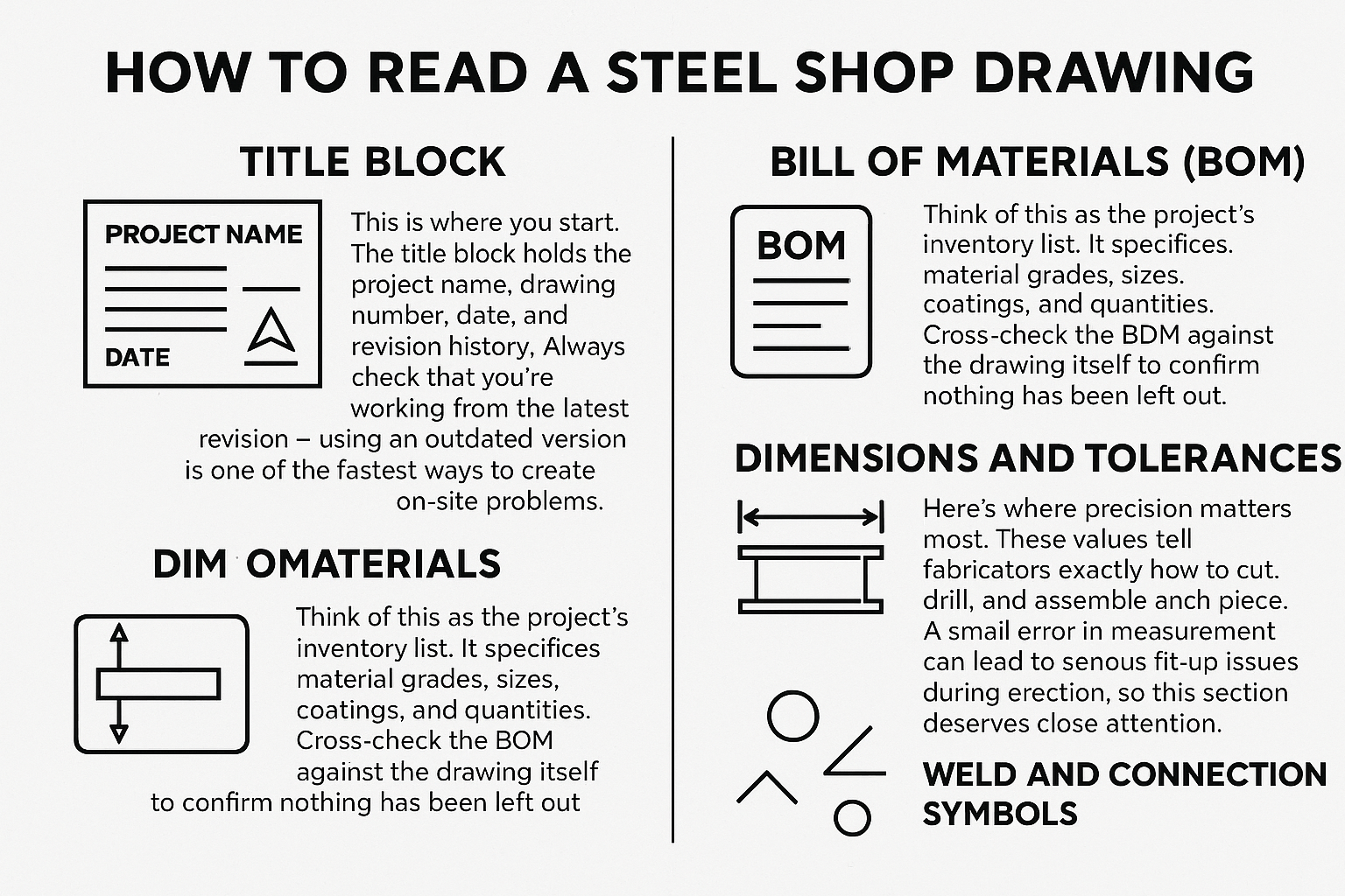
Steel shop drawings can look intimidating at first glance, but once you break them down into parts, they’re far easier to interpret. Each section has its own purpose, and moving through them step by step gives you the full picture.
Title Block
This is where you start. The title block holds the project name, drawing number, date, and revision history. Always check that you’re working from the latest revision – using an outdated version is one of the fastest ways to create on-site problems.
Bill of Materials (BOM)
Think of this as the project’s inventory list. It specifies material grades, sizes, coatings, and quantities. Cross-check the BOM against the drawing itself to confirm nothing has been left out.
Dimensions and Tolerances
Here’s where precision matters most. These values tell fabricators exactly how to cut, drill, and assemble each piece. A small error in measurement can lead to serious fit-up issues during erection, so this section deserves close attention.
Weld and Connection Symbols
The symbols may be compact, but they carry critical instructions about how components must be joined. They cover weld types, sizes, and bolt details. It’s worth taking the time to verify these against recognized standards before moving forward.
Frequent Errors in Steel Shop Drawings and How to Prevent Them
Even experienced teams can run into mistakes with shop drawings. The key is knowing where those mistakes usually happen and having checks in place to catch them early.
Missing or Wrong Dimensions
When a drawing leaves out critical measurements, fabrication teams are forced to guess, which usually leads to costly rework.
- Cause: Drawings prepared too quickly or skipped reviews
- Fix: Verify all dimensions against the structural plans and material list before sign-off
Misread Symbols
Symbols carry instructions for welds, bolts, and cuts, but if they’re unclear or interpreted incorrectly, the result is weak or unsafe connections.
- Cause: Inconsistent use of standards or lack of symbol familiarity
- Fix: Follow AWS or AISC standards consistently and provide clear reference sheets for teams
Outdated Versions
Fabrication or erection done with an old revision almost guarantees mismatches on site.
- Cause: Poor document control or reliance on printed copies
- Fix: Store and update drawings in a centralized system where the latest version is always accessible
Lack of Trade Coordination
Steel doesn’t exist in a vacuum. If shop drawings ignore MEP, concrete, or architectural details, clashes are inevitable.
- Cause: Separate teams working in silos
- Fix: Integrate shop drawings with BIM coordination models and hold multi-discipline reviews
The Future of Steel Shop Drawings
Steel shop drawings are shifting from static 2D sheets to more dynamic, data-rich formats. With Building Information Modeling (BIM) now central to many projects, shop drawings are increasingly tied directly to 3D models. Instead of being a separate deliverable, they become an extension of the model itself, carrying all the fabrication and installation details within a single coordinated environment. This reduces the risk of misalignment between design and production and gives every team access to the same source of truth.
Automation is also reshaping how these drawings are prepared. Rule-based detailing, parametric design, and scripting tools allow repetitive tasks to be completed faster and with fewer errors. What once took hours of manual drafting can now be generated in minutes, freeing up engineers and detailers to focus on complex connections and project-specific challenges.
Looking ahead, shop drawings won’t disappear, but their role will keep evolving. They’ll act less like static blueprints and more like interactive guides that plug into digital workflows. For teams willing to adopt BIM-driven processes and automation, this shift means greater efficiency, tighter coordination across trades, and fewer surprises once steel arrives on site.
Conclusion
Steel shop drawings may not be the most glamorous part of a project, but they’re the backbone that holds everything together. They take broad design intent and turn it into instructions that fabricators and installers can actually build from. When done right, these drawings save time, prevent errors, and keep projects moving in the right direction.
As construction becomes more digital, shop drawings are evolving too. BIM integration and automation are already changing how they’re produced and used, but their purpose stays the same: giving every team a clear path from concept to construction. For any project that relies on steel, shop drawings aren’t just helpful – they’re essential.
FAQ
What makes steel shop drawings different from design drawings?
Design drawings set out the overall concept and structural intent, while shop drawings break that intent down into step-by-step fabrication and installation instructions.
Who is usually responsible for preparing shop drawings?
They’re typically prepared by steel detailers or fabricators, with engineers and architects reviewing and approving them for accuracy and compliance.
Why are revisions so important in shop drawings?
A single outdated sheet can lead to fabrication mistakes or clashes on site. That’s why version control and clear communication are critical.
Do shop drawings always have to follow standards?
Yes, they must comply with regional standards such as AISC and AWS in the USA, Eurocode in Europe, or other applicable standards depending on the project.
How is BIM changing the role of shop drawings?
Instead of being just 2D sheets, shop drawings are now often tied directly to 3D models, making them part of a single coordinated workflow.
Our Case Studies
We have handled 200+ BIM & VDC projects for commercial, industrial, and residential sectors.
Our work includes:
Formwork design automation
Our client from
California, USA
Suspended ceiling design automation
Our client from
New York, USA
Wall framing design automation
Our client from
California, USA