Have any questions? Contact us!
Join our team!
Request a free quote or consultation

What Structural Shop Drawings Are and Why They Matter in Construction
Structural shop drawings translate design intent into fabrication-ready detail. These aren’t high-level concepts or visualizations – they’re the documents that tell builders exactly what to do. With dimensions, materials, welding specs, and connection details packed into every sheet, shop drawings make construction workflows clearer, faster, and less prone to error. They’re what keep structural teams aligned when the margin for mistakes is zero.
Understanding Structural Shop Drawings: What's Inside and Why It Matters
Structural shop drawings are what turn design concepts into something buildable. They’re not there to impress – they’re there to guide real work. These are the detailed documents that steel fabricators, concrete crews, and installation teams rely on to know what to cut, weld, pour, or bolt down. Every drawing is tailored to the exact specs of the project, taking the general intent of an architect or engineer and translating it into production-level detail.
What’s actually in a shop drawing? Quite a bit. You’ll find precise measurements for beams, columns, and joints. You’ll see the type of materials to use, how parts connect, where welds go, and what bolts are needed – including their size and spacing. Elevations, sections, and zoomed-in detail views all help make sense of how each component fits into the larger structure. Revision logs, drawing numbers, and load requirements are typically there too.
It’s not about making things pretty; it’s about getting them right. Without these drawings, coordination between teams gets messy fast, and small errors can snowball into major delays or rework. So, while they may not get much attention outside the jobsite, they’re one of the most critical tools in the construction workflow.
What You’ll Actually Find Inside a Structural Shop Drawing
Structural shop drawings aren’t just lines on paper – they’re working instructions for fabrication and installation. Every detail in them is there for a reason, and when something’s missing, things go sideways fast. Here’s what a solid structural shop drawing typically includes:
- Exact dimensions for beams, columns, bracing, and other load-bearing elements.
- Material specifications, right down to the steel grade or concrete mix.
- Connection details, showing how parts will be welded, bolted, or anchored together.
- Bolt types, sizes, and spacing, usually matched to project-specific loads.
- Welding symbols and instructions, often including length, location, and orientation.
- Sections, elevations, and detail views that zoom in on critical junctions or transitions.
- Rebar detailing if the drawing includes reinforced concrete components.
- Drawing and revision numbers to track updates and ensure version control.
- Referenced standards or codes, so everyone’s on the same page when it comes to compliance.
- Notes and fabrication instructions, which sometimes include installation sequencing or tolerances.
These aren’t “nice to have” – they’re required if you want to avoid field changes, last-minute RFIs, and unhappy contractors. The clearer the drawing, the smoother the job runs.
Where Precision Meets Execution: Structural Drafting by Powerkh

Powerkh is a structural detailing company based in the UK, with additional offices in Ukraine and the USA. We deliver precise 3D models and structural shop drawings that help contractors and fabricators get their builds right the first time. Our work centers on Building Information Modeling (BIM), allowing us to spot design issues early and provide clean, build-ready documentation.
Our structural shop drawing packages typically include fabrication-level detail, bills of materials, and accurate takeoffs – everything needed to move from design to installation with fewer surprises. We cover steel detailing, rebar layouts, precast and prefab elements, and concrete outlines. For more complex systems, we also handle curtain wall detailing and BIM coordination, working closely with project teams to keep everything aligned.
We support commercial, industrial, and residential projects across the UK, USA, and Europe. Whether it’s formwork automation or large-scale wall framing, our team brings a mix of engineering know-how and modeling expertise to deliver exactly what’s needed – drawings that don’t just look good, but actually work on site.
Who’s Actually Behind Structural Shop Drawings
Shop drawings don’t just appear out of thin air – they’re usually built by detailers or drafting specialists who live deep in the technical side of construction. These professionals take the structural engineer’s design intent and translate it into a format that fabricators and installers can work with. Think less about sweeping design vision and more about “here’s exactly how this gets built.”
In most cases, it’s a dedicated drafting team or detailing firm doing the heavy lifting. They work closely with structural engineers to make sure nothing gets lost in translation. Some larger contractors and steel fabricators handle this in-house, especially if the workflows are standardized or fast-paced. Others outsource to specialists who know the ins and outs of steel, concrete, or rebar detailing – and who spend most of their day inside Revit, Tekla, or AutoCAD.
It’s not just about drawing lines. It’s about understanding construction logic, tolerances, sequencing, and how things will come together on site. The best drafters spot potential issues before anyone sets foot on a jobsite – and that’s where the real value is.
Common Types of Structural Shop Drawing Views
Good shop drawings don’t just list measurements – they show the structure from every angle that matters. Different views serve different purposes, and each one helps avoid questions later when materials are being cut, welded, or installed. Here’s a breakdown of the key views you’re likely to see in a structural set.

1. Elevation Views
These show the structure from the front, side, or back – like standing in front of a wall or frame. Elevation views help teams understand vertical relationships between components and where openings, braces, or beam lines sit.
Typically include:
- Height dimensions for columns and walls
- Placement of beams, openings, and connections
- Vertical alignment between floors or levels
- Any façade elements that affect structure
2. Section Views
Sections cut through the structure to show what’s going on inside – usually along a key plane. These are critical for understanding how components are layered and how different materials or systems interact.
Typically include:
- Depth of foundations or footings
- Floor slab and decking thickness
- Overlapping connections between beams and columns
- Reinforcement layout or embed placements
3. Detail Views
Detail views zoom in on specific areas that need more explanation. When a joint is complex or there’s a tight clearance, this is where you’ll find the answers.
Typically include:
- Bolt patterns, plate sizes, and welds
- Edge conditions and fasteners
- Custom brackets or stiffeners
- Tolerances or instructions for field adjustment
4. Plan Views
Plan views look down at the structure from above. They’re often the first reference when laying out a frame or checking overall dimensions.
Typically include:
- Beam and joist layout
- Column grid and spacing
- Anchor bolt plans
- Elevation callouts that link to other views
5. Isometric or 3D Views
Not always required, but helpful – especially for complex assemblies. These views provide a more intuitive picture of how parts fit together in space.
Typically include:
- Spatial arrangement of components
- Connection geometry
- Overlap or clash-prone areas
- Supporting notes for fabrication teams
Each of these views plays a role in making the drawing set readable and useful. Skip one, and something important could get misinterpreted on site. When they’re all working together, teams don’t have to guess – they just build.
Keeping Structural Drawings Clean, Clear, and Compliant
A well-made shop drawing isn’t just precise – it’s accountable. Before any part gets fabricated or shipped to site, the drawing goes through multiple layers of quality control. It’s how teams catch errors early, avoid confusion on the floor, and meet legal and safety standards without surprises.
![]()
Technical Review: Are the Numbers Right?
This is the first line of defense. Drafters and engineers check that dimensions, materials, and notes all match the design intent. Every connection detail, bolt spec, and material callout needs to line up – not just with the drawing itself, but with the bigger project context. If something’s off, it gets flagged before anyone cuts steel.
Design Coordination: Does It Actually Fit?
Even if a drawing looks clean, it needs to work in the real world. That means checking how it connects with surrounding elements – and with drawings from other trades. This is where clash detection and cross-referencing come in. If a beam runs through ductwork or two trades fight for the same anchor point, it gets fixed now – not during install.
Code & Standards Check: Is It Legal?
Different regions, different rules. Whether it’s AISC, Eurocode, AS/NZS, or a custom spec from the project owner, the drawing has to reflect the standards that apply. Load paths, weld symbols, connection types – everything has to pass this check before it goes out the door. This step is non-negotiable.
Engineer Approval: Is It Safe to Build?
The final stamp usually comes from the engineer of record. Their signature confirms the drawing aligns with the structural design and complies with safety standards. Without that sign-off, the drawing doesn’t move. It’s not just a formality – it’s legal protection for everyone involved.
Traceability: Can You Defend It Later?
If something goes wrong on site, people go back to the drawings. That’s why version control, revision numbers, and approval logs matter. Every update needs to be tracked, dated, and documented – otherwise it’s just someone’s best guess.
Where Shop Drawings Fit in the Construction Workflow
Structural shop drawings don’t come first – but they’re the point where things start getting real. After the initial design and engineering phase wraps up, these drawings bridge the gap between concept and execution. They take the structural intent and turn it into buildable instructions, with enough detail to fabricate steel, pour concrete, and prep the site. Nothing gets made without them – not if you’re aiming for precision.
They’re also a coordination checkpoint. While the design team lays out what needs to happen, shop drawings show how it’ll happen – especially when multiple trades are involved. Structural steel has to avoid MEP systems. Anchors have to line up with rebar. The shop drawing stage is where those conflicts get flagged and resolved, long before crews hit the jobsite. In short, it’s not just a drawing – it’s a control tool. Get it right here, and the rest of the workflow moves faster, cleaner, and with fewer surprises.
Conclusion
They might not be flashy, but structural shop drawings are one of the few things on a project that actually keep everything on track. They’re the documents that connect design intent with physical execution – spelling out what gets built, how, and with what materials. Without them, a project risks becoming a guessing game.
The best shop drawings reduce confusion, prevent rework, and give every team – from fabricators to field crews – a shared reference point. When done right, they save time, cut down on errors, and make sure the structure you’re putting up actually works the way it’s supposed to. It’s not glamorous, but it’s critical.
FAQ
1. What’s the difference between design drawings and shop drawings?
Design drawings focus on what a building should look like and how it’s intended to perform. Shop drawings, on the other hand, show how to actually build it – down to the nuts, bolts, and welds. They’re made for fabrication, not just visualization.
2. Are structural shop drawings always required?
Not in every project, but for anything involving custom fabrication, steelwork, or complex assemblies – yes. Without them, it’s almost impossible to guarantee fit, compliance, or coordination across trades.
3. Who approves structural shop drawings?
The final sign-off usually comes from the engineer of record. But before that, drawings are reviewed by drafters, coordinators, and often the general contractor. Everyone needs to be aligned before fabrication begins.
4. Can shop drawings be used for permitting?
Usually not. Permitting is typically based on architectural and structural design drawings. Shop drawings are too detailed and task-specific – they’re made for fabrication and internal use, but may require separate review or approval by authorities in some jurisdictions for specific components.
5. What software is used to create shop drawings?
Most teams use tools like AutoCAD, Revit, Tekla, or Advance Steel. The choice depends on the material (steel, concrete, rebar) and how the firm handles its detailing workflows.
6. What happens if shop drawings aren’t accurate?
Things get expensive, fast. Misalignments, clashes, and fabrication errors lead to delays, change orders, and potential safety risks. That’s why quality control and version tracking are essential.
Our Case Studies
We have handled 200+ BIM & VDC projects for commercial, industrial, and residential sectors.
Our work includes:
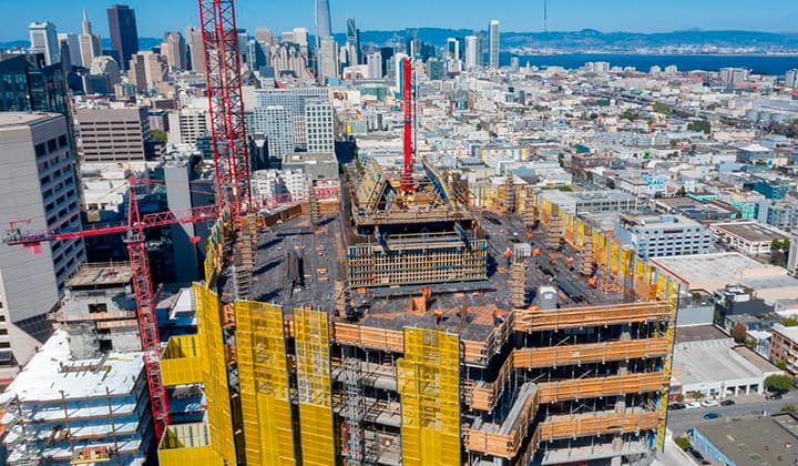
Formwork design automation
Our client from
California, USA
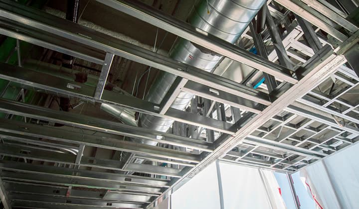
Suspended ceiling design automation
Our client from
New York, USA
Wall framing design automation
Our client from
California, USA