Have any questions? Contact us!
Join our team!
Request a free quote or consultation

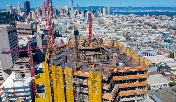
Imagine you’re on a construction site, watching a massive steel framework rise from the ground, each beam fitting perfectly like a puzzle piece. Ever wonder how that happens without chaos? The answer lies in fabrication shop drawings. These aren’t just sketches – they’re the detailed, technical blueprints that tell fabricators exactly how to craft, assemble, and install components for a project. Whether it’s a skyscraper’s skeleton or a custom kitchen cabinet, these drawings are the unsung heroes ensuring everything comes together without a hitch. As someone who’s seen countless projects unfold, I can tell you: they’re the glue between a designer’s vision and the reality you can touch. Let’s dive into what makes them tick, why they’re critical, and how they fit into today’s high-tech construction world.
The Heart of Fabrication Shop Drawings: What They Do
Fabrication shop drawings are specialized technical documents that bridge the gap between conceptual design and physical construction. They provide fabricators with precise instructions to manufacture individual components, assemble them, and install them on-site. Think of them as a translator: they take an architect’s or engineer’s broad plans and break them down into actionable, inch-by-inch details for the shop floor.
These drawings are laser-focused on the manufacturing process. Unlike general architectural plans that show the big picture – like where walls or HVAC systems go – these zoom in on specific parts. For example, they might detail a single steel beam’s dimensions, the exact welds needed, or how a custom duct fits into a ventilation system. They’re crafted by skilled drafters or CAD technicians, often using advanced software, to eliminate guesswork. In my experience, when these drawings are done right, they can save hours of frustration and thousands in rework costs.
Why They Matter
- Precision: They ensure every cut, weld, or bolt is exactly as designed, reducing errors that could derail a project.
- Communication: They create a shared language for designers, engineers, and fabricators, cutting down on misunderstandings.
- Efficiency: Clear instructions speed up manufacturing and installation, keeping timelines tight.
- Compliance: They align with industry standards, ensuring safety and regulatory adherence.
Powerkh’s Guide to Fabrication Shop Drawings Excellence

Powerkh is a UK-based company that provides BIM (Building Information Modeling) services focused on prefabrication and fabrication in modular construction. Our company also has offices in Ukraine, and the USA, we work with clients across various regions to support architectural, structural, and MEP (Mechanical, Electrical, and Plumbing) aspects of construction. Our goal is to optimize manufacturing processes, improve project timelines, and enhance coordination using advanced digital tools.
At Powerkh, we specialize in creating detailed 3D prototypes and automating repetitive tasks to streamline modular construction. By allowing manufacturing and on-site work to proceed simultaneously, we help reduce project turnaround times. Our approach minimizes waste, ensures material accuracy, and improves safety by enabling off-site assembly in controlled environments. We work with clients in the industrial, commercial, and residential sectors.
Our services include BIM development for CNC manufacturing, design drafting, shop drawings, clash detection, and design-to-fabrication workflows. We use software such as Autodesk Revit, Dynamo, and Tekla to deliver accurate models and support project coordination. By aligning the efforts of engineers, fabricators, and construction teams, we help ensure that projects are completed efficiently and meet all required specifications.
Key Highlights:
- UK-based company with offices in the USA and Ukraine, specializing in prefabrication and fabrication BIM services.
- Supports modular construction by creating detailed 3D prototypes and automating tasks.
- Expertise in architectural, structural, and MEP aspects of construction.
- Focuses on reducing project timelines, minimizing waste, and ensuring material accuracy.
- Works across industrial, commercial, and residential sectors.
Core Components of Fabrication Shop Drawings
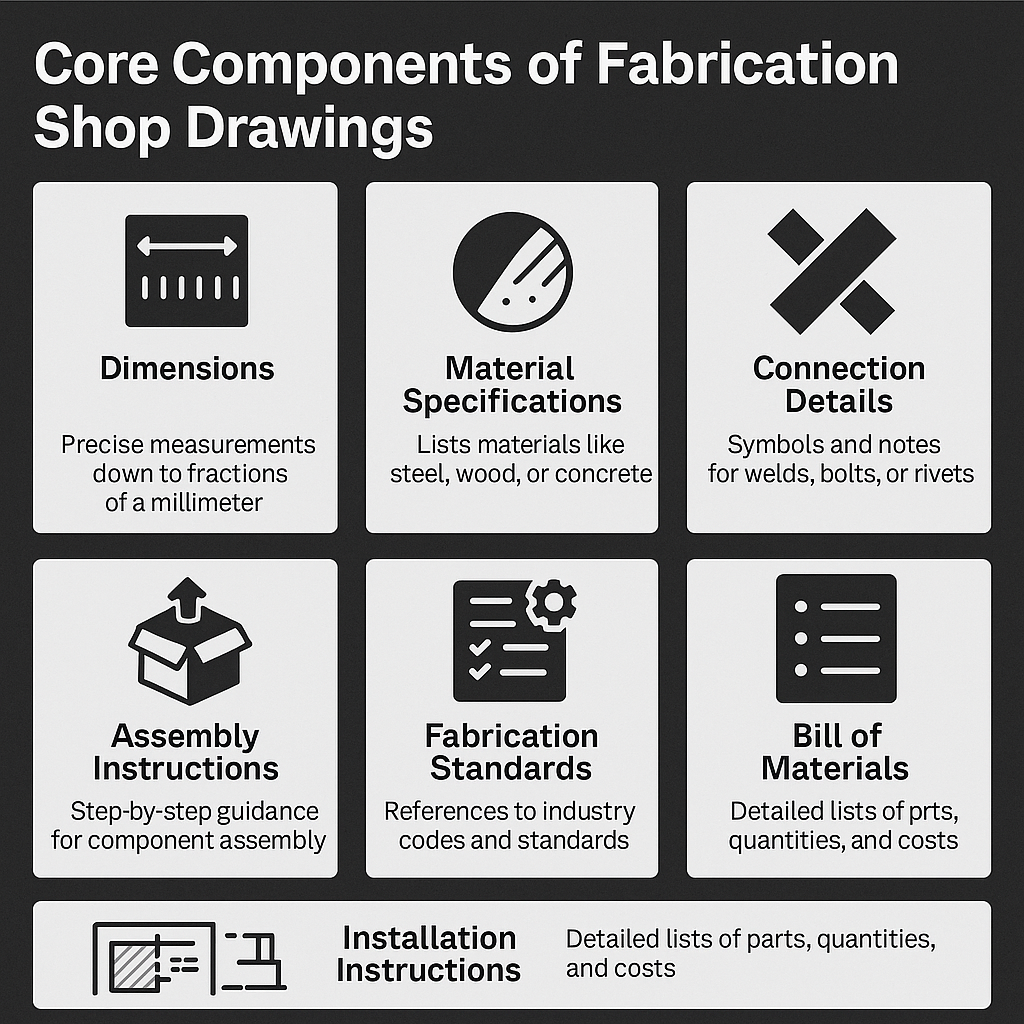
To understand what makes these drawings so effective, let’s break down their key elements. Each one plays a critical role in guiding the fabrication process, and missing even one can lead to costly mistakes.
Dimensions
Every measurement is spelled out with pinpoint accuracy – down to fractions of a millimeter. This includes lengths, widths, depths, and even the placement of holes or notches. For instance, a steel column’s drawing might specify its exact height and the precise location of bolt holes for connections.
Material Specifications
The drawings detail exactly what materials to use, like a specific grade of stainless steel or a type of hardwood for millwork. This ensures the component meets strength, durability, and aesthetic requirements. I’ve seen cases where vague material specs led to using the wrong alloy, causing delays – so clarity here is non-negotiable.
Connection Details
How parts join together is critical. These drawings include symbols and notes for connections like welds, bolts, or rivets. For example, a welding drawing might specify the type of weld (fillet or butt) and its size, ensuring structural integrity. Getting this wrong can weaken a structure, so precision is everything.
Assembly Instructions
Step-by-step guidance on how to put components together is included, often with exploded views or sequence diagrams. This is especially useful for complex assemblies, like a modular facade system, ensuring every piece fits as intended before it leaves the shop.
Fabrication Standards
These drawings reference industry codes (like AISC for steel or ASME for mechanical components) to ensure compliance with safety and quality standards. This is crucial in regulated industries like aerospace or healthcare, where deviations can have serious consequences.
Installation Instructions
Beyond manufacturing, the drawings guide how components are installed on-site. For example, they might show how a precast concrete panel aligns with a building’s frame, including anchor points and tolerances.
Bill of Materials
A detailed list of all parts and quantities needed, from bolts to sheet metal, helps fabricators plan inventory and avoid shortages. This also aids in cost estimation, keeping budgets in check.
- Tip for Clarity: Use consistent labeling and symbols across drawings to avoid confusion.
- Common Oversight: Forgetting to update the bill of materials after design changes – always double-check!
- Tech Advantage: 3D annotations in modern software can make complex details easier to visualize.
These elements work together to create a document that’s both comprehensive and practical, guiding fabricators through every step of the process.
How Fabrication Shop Drawings Differ from Related Documents
It’s easy to lump all technical drawings together, but fabrication shop drawings have a unique role. Understanding how they differ from similar documents helps clarify their value.
Vs. Shop Drawings
Shop drawings are broader, focusing on how components integrate into the entire project. For example, a shop drawing might show how an HVAC system fits into a building’s layout, including duct routes and connections to other systems. Fabrication shop drawings, however, drill down to the manufacturing and assembly of specific parts, like a single duct section, with detailed instructions for cutting and welding. While all fabrication shop drawings are a type of shop drawing, not all shop drawings are fabrication-focused.
Vs. Fabrication Drawings
Pure fabrication drawings are about the manufacturing process – think tolerances, material specs, and production details for a single component. Fabrication shop drawings go a step further, including assembly and installation instructions. For instance, a fabrication drawing might detail how to machine a steel plate, while a fabrication shop drawing adds how that plate fits into a larger assembly and gets installed on-site.
Vs. Assembly Drawings
Assembly drawings show how multiple components come together to form a complete product, like a machine or a roof truss system. Fabrication shop drawings might focus on just one piece of that puzzle, providing granular details for its creation and installation. For example, an assembly drawing shows the entire truss, while a fabrication shop drawing details one beam within it.
Vs. Welding Drawings
Welding drawings are hyper-specific, focusing solely on weld types, sizes, and locations. Fabrication shop drawings include welding details but cover broader aspects like dimensions, materials, and installation.
- Key Takeaway: Fabrication shop drawings balance manufacturing precision with practical assembly and installation guidance, making them versatile for shop and site use.
- Practical Note: When coordinating a project, ensure your team knows which drawing type is needed to avoid overlap or gaps in information.
This distinction matters because it affects who uses the drawings and how. Misusing them can lead to miscommunication, so clarity in scope is crucial.
The Creation Process: Crafting Fabrication Shop Drawings
Making these drawings is a careful, step-by-step process that blends art, science, and collaboration. Here’s how it typically goes down:
- Gather Design Inputs: Drafters start by reviewing architectural and engineering plans to understand the project’s scope and intent. This includes studying structural layouts, MEP designs, or product specs.
- Draft Initial Versions: Using software like AutoCAD, Revit, or SolidWorks, CAD technicians create detailed drawings. They input precise measurements, material specs, and connection details, often starting with a 3D model for accuracy.
- Collaborate and Refine: Engineers and fabricators provide feedback to ensure the drawings are practical and meet design goals. This back-and-forth catches errors early, like a misaligned bolt hole that could cause issues later.
- Incorporate Standards: The team ensures compliance with industry codes and local regulations, referencing standards like those from the American Welding Society or building codes.
- Finalize and Distribute: After revisions, the drawings are finalized and shared digitally with fabricators, often in formats like PDF or DWG for easy access.
From my perspective, involving fabricators early in this process is a game-changer. They bring real-world insights – like spotting a design that’s tough to build – that desk-bound drafters might miss. Modern tools also make a difference; automating repetitive tasks with scripts can cut drafting time significantly.
The Role of Technology: BIM and Beyond
Today’s fabrication shop drawings aren’t stuck in the 2D world – they’re part of digital ecosystems like Building Information Modeling (BIM) and Virtual Design and Construction (VDC). These technologies supercharge their impact.
BIM Integration
In BIM, drawings are generated from 3D models that contain rich data – think dimensions, materials, and even cost estimates. Models can reach LOD (Level of Detail) 500, meaning every detail is nailed down for fabrication and installation. This reduces errors by letting teams visualize components in context.
Clash Detection
BIM software like Revit can spot conflicts – like a duct clashing with a beam – before fabrication begins. This saves time and money compared to fixing issues on-site.
Automation
Tools like Dynamo automate repetitive tasks, such as generating cutting lists or updating dimensions across drawings. This speeds up production and reduces human error.
Prefabrication
For off-site manufacturing, these drawings feed directly into CNC machines, turning digital plans into physical parts with precision. This is huge for components like steel panels or precast concrete.
3D Visualization
Some drawings include 3D views or annotations, making complex assemblies easier to understand. This is especially helpful for intricate systems like MEP setups.
I’ve seen projects where BIM cut coordination time by half, simply because everyone could “see” the design in 3D before breaking ground. If you’re new to this, starting with a small BIM pilot – like modeling a single system – can ease the transition.
Why Fabrication Shop Drawings Are a Big Deal
So, why invest time and resources in these drawings? Because they deliver benefits that ripple across the entire project lifecycle.
Error Reduction
By providing exact specs, they minimize mistakes. A mis-cut beam or a wrong weld can cost thousands to fix; these drawings help avoid that.
Enhanced Communication
They create a clear channel between designers, engineers, and fabricators. Everyone’s on the same page, reducing back-and-forth and delays.
Streamlined Workflow
Clear instructions mean fabricators can work faster, and installers know exactly what to do on-site. This keeps projects on schedule.
Cost Savings
Accurate material lists and cutting plans reduce waste, while early clash detection prevents costly rework. They also aid in precise budgeting and bidding.
Quality Assurance
Inspectors use these drawings to verify that components meet specs, ensuring high-quality outcomes.
Regulatory Compliance
By referencing industry standards, they ensure components meet safety and legal requirements, critical in fields like healthcare or aerospace.
Documentation
They serve as a permanent record for maintenance, repairs, or future renovations, making life easier down the road.
One thing I’ve noticed: teams that prioritize these drawings report fewer headaches. On a recent project, detailed drawings caught a design flaw early, saving weeks of rework. They’re not just paperwork – they’re problem-solvers.
Real-World Applications Across Industries
These drawings shine in a variety of scenarios, adapting to different project needs. Here’s a look at where they make an impact:
- Structural Steel: Detail beams, columns, and connections for buildings or bridges, ensuring strength and fit.
- Millwork: Specify cuts, joins, and finishes for custom cabinets or furniture, perfect for residential or hospitality projects.
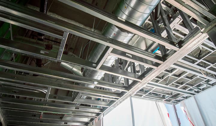
- HVAC Systems: Map out ducts and fittings, with welding and installation details to ensure efficiency.
- Precast Concrete: Guide the creation and placement of panels or slabs, critical for modular construction.
- Facade Systems: Detail cladding or curtain walls for commercial buildings, balancing aesthetics and function.
In smaller projects, like residential decks, they optimize material cuts to reduce waste. In massive builds, like industrial plants, they coordinate complex assemblies. Their versatility is what makes them indispensable.
Overcoming Common Challenges
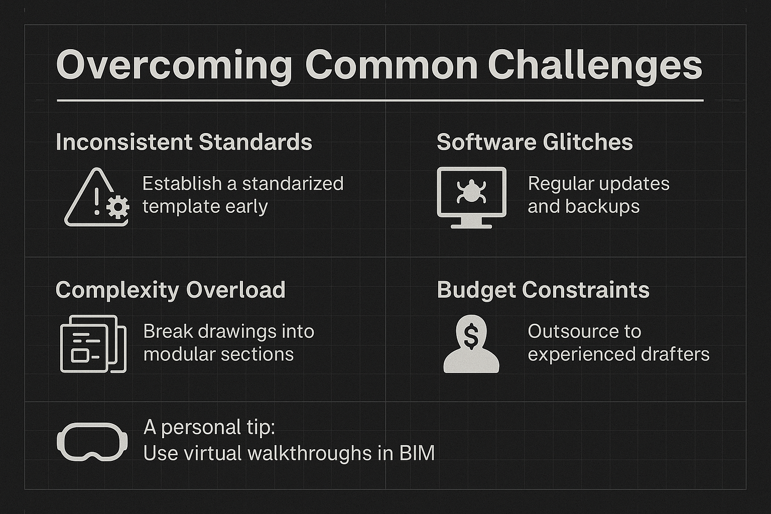
Nothing’s perfect, and these drawings come with challenges. Here are a few, along with ways to tackle them:
Inconsistent Standards
Different teams might use varying formats or symbols. Solution: Establish a standardized template early and train everyone on it.
Software Glitches
Digital tools can hiccup, like misaligned exports. Regular software updates and backups help, as does testing outputs before finalizing.
Complexity Overload
Large projects can produce overwhelming drawings. Break them into modular sections – like separating structural and MEP details – for clarity.
Budget Constraints
High-quality drawings take time and skill. Outsourcing to experienced drafters can balance cost and quality, delivering fast turnarounds.
A personal tip: use virtual walkthroughs in BIM to spot issues before finalizing drawings. It’s like a dress rehearsal for your project.
The Future: Where Fabrication Shop Drawings Are Headed
As we move through 2025, these drawings are evolving with technology. Automation is picking up speed, with AI tools generating initial drafts or optimizing layouts. Generative design could soon offer multiple design options automatically, saving time.
Augmented reality (AR) and virtual reality (VR) are also entering the scene, letting teams preview assemblies in a virtual space before building. Imagine walking through a digital model to check how a truss fits – it’s game-changing.
Internet of Things (IoT) integration could make drawings dynamic, updating in real-time as project conditions change. This is still emerging but holds huge potential.
For now, embracing BIM and automation is the way to go. It’s not just about keeping up – it’s about staying ahead in a competitive field.
Wrapping It Up: The Power of Fabrication Shop Drawings
Fabrication shop drawings are more than technical documents – they’re the backbone of precision, communication, and efficiency in construction. They turn ideas into reality, ensuring every piece fits, every weld holds, and every project succeeds. Whether you’re building a high-rise or a custom kitchen, these drawings are your roadmap to getting it right.
If you’re new to this, start by reviewing your current process. Could clearer drawings save time or money? For veterans, consider how tech like BIM can take your drawings to the next level. Either way, they’re worth the effort – they’re the difference between a project that stumbles and one that soars.
Frequently Asked Questions (FAQs)
What’s the difference between fabrication shop drawings and regular shop drawings?
Fabrication shop drawings focus on manufacturing, assembling, and installing specific components, with detailed specs for production. Regular shop drawings cover broader integration, like how systems fit into a project’s layout, with less emphasis on manufacturing details.
Who creates fabrication shop drawings?
They’re typically created by skilled drafters or CAD technicians, often with input from engineers and fabricators. Modern software like Revit or AutoCAD is used to ensure accuracy and incorporate 3D modeling.
Why are fabrication shop drawings important for construction?
They ensure precision in manufacturing, reduce errors, streamline communication, and support compliance with safety standards. They also save costs by minimizing rework and optimizing material use.
Can fabrication shop drawings be used for maintenance?
Yes, they serve as a detailed record of how components were built and installed, making them valuable for future repairs, renovations, or audits.
Our Case Studies
We have handled 200+ BIM & VDC projects for commercial, industrial, and residential sectors.
Our work includes:
Formwork design automation
Our client from
California, USA
Suspended ceiling design automation
Our client from
New York, USA
Wall framing design automation
Our client from
California, USA