Have any questions? Contact us!
Join our team!
Request a free quote or consultation

Steel fabrication drawings are the unsung heroes of construction, turning raw steel into sturdy beams, columns, and frames that hold up buildings, bridges, and more. I’ve been around construction long enough to know these aren’t just sketches – they’re detailed guides that tell fabricators exactly how to cut, shape, and assemble steel so everything fits perfectly. Mess this up, and you’re looking at misaligned parts, wasted materials, or worse, safety issues. They’re like the recipe for a complex dish – one wrong measurement, and the whole thing falls apart.
These drawings pack in specifics: dimensions, materials, how pieces connect, and even what tolerances are allowed. They bridge the gap between an architect’s vision and the reality of a finished structure. In today’s world, where projects demand precision and speed, these blueprints are often paired with digital tools like 3D modeling to catch mistakes before they cost you time or money. If you’re involved in construction – whether as a designer, contractor, or engineer – understanding these drawings is key to keeping your project on track.
Unpacking the Key Components
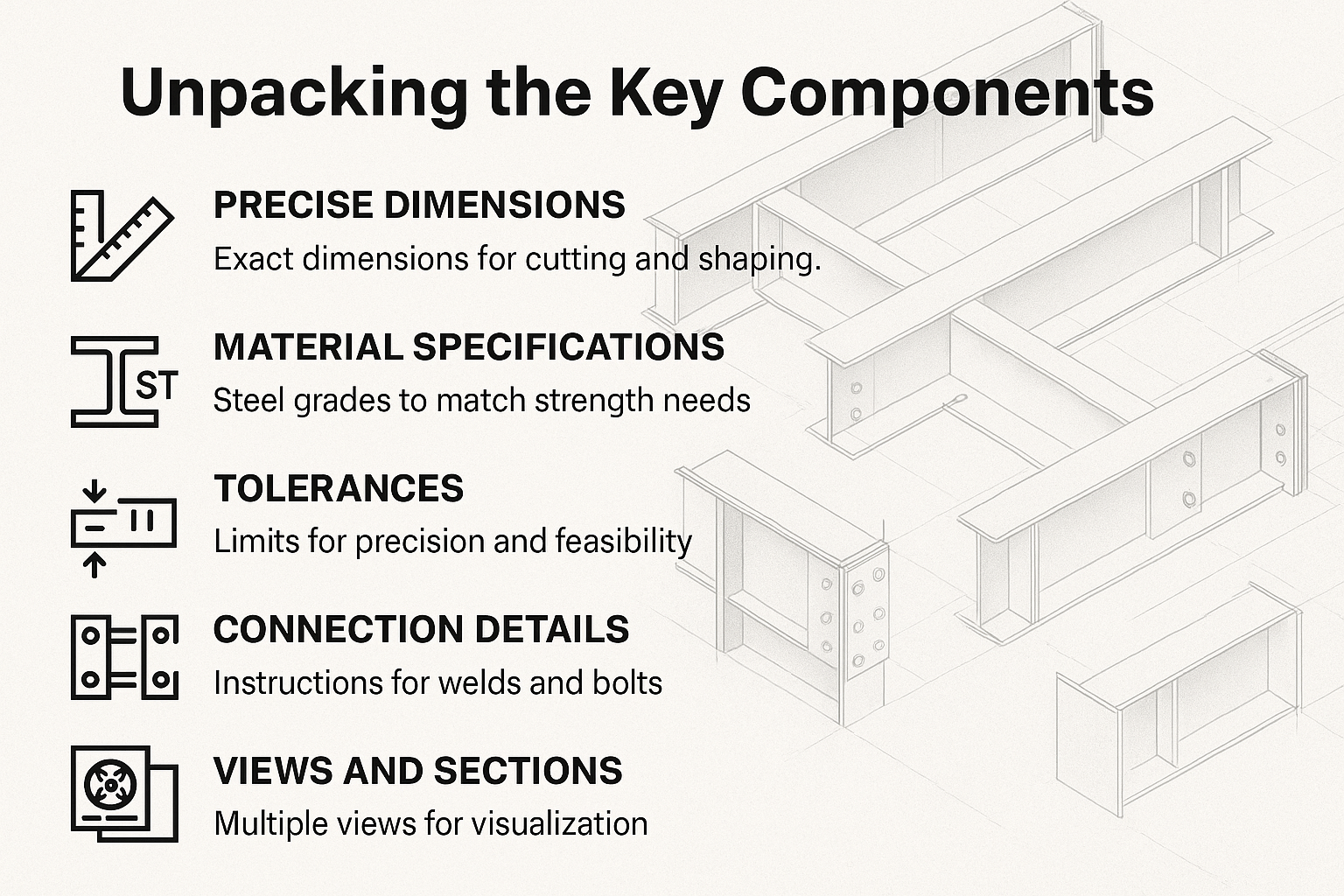
A steel fabrication drawing is like a Swiss Army knife – it’s got multiple tools, each with a specific job. Let’s break down what goes into one, because knowing these parts helps you appreciate why they’re so critical.
Precise Dimensions
Every drawing starts with exact measurements. We’re talking lengths, widths, angles – down to the millimeter. These aren’t guesses; they’re the numbers fabricators rely on to cut steel accurately. A single error here can throw off an entire assembly, so precision is everything.
Material Specifications
Next up, the drawing spells out what kind of steel to use – its grade, strength, and any special treatments like galvanizing for rust protection. This ensures the steel can handle the job, whether it’s supporting a skyscraper or enduring harsh weather.
Tolerances
Tolerances are the wiggle room allowed in measurements. Too tight, and fabrication becomes a nightmare; too loose, and the structure might not hold up. They’re usually noted with plus-or-minus values to keep things practical but safe.
- Exact dimensions for cutting and shaping.
- Steel grades to match strength needs.
- Tolerances to balance precision and feasibility.
Connection Details
This is where the drawing gets into how pieces join – think welds (like fillet or groove) or bolts (shear or tension types). It specifies sizes, placements, and even weld quality to ensure the structure stays solid under stress.
Views and Sections
To make sense of complex parts, drawings include multiple angles – top, side, or cross-sectional views. These show details that might be hidden, helping fabricators and assemblers visualize the component fully.
Bill of Materials
A bill of materials lists every item needed, from steel plates to nuts and bolts. It’s a checklist that prevents shortages and keeps costs in check. Skipping this is like trying to cook without knowing if you’ve got all the ingredients.
Using digital tools, these components can be modeled in 3D, letting you spot issues before any steel is cut. It’s a small step that saves big headaches later.
Powerkh's Precision Blueprint: Crafting Steel Fabrication Drawings

Powerkh is a UK-based company with offices in Ukraine and the USA, specializing in steel shop drawings and structural detailing. We provide precise and detailed steel drawings tailored to the needs of each project, ensuring alignment with architectural and engineering requirements. Our services are designed to support a variety of industries throughout the design and construction stages, offering clear, accurate documentation for steel structures.
Our team produces comprehensive shop drawings for critical steel components, including framing, connections, and foundations. These drawings serve as essential guidelines for fabrication and construction teams, ensuring proper assembly and minimizing errors. We use advanced software tools to create detailed, high-quality drawings that facilitate efficient communication and coordination across all project stakeholders.
Beyond detailing, we also offer project coordination services, addressing any challenges that arise during the construction process. Our approach helps ensure projects proceed smoothly, with accurate and reliable documentation that reduces the risk of delays and costly revisions.
Key Highlights:
- UK-based company with offices in Ukraine and the USA
- Specializes in steel shop drawings and structural detailing
- Supports a variety of industries with tailored steel detailing services
- Provides high-quality, precise drawings to guide fabrication and construction
- Uses advanced software tools for accurate, error-free documentation
- Offers project coordination to streamline the construction process
Why These Drawings Matter in Construction
Steel fabrication drawings are the glue that holds a project together. They take high-level designs and break them down into instructions that workshops and job sites can actually use. Without them, you’d have fabricators guessing how to build parts, leading to costly rework or delays.
They start by guiding the fabrication process – cutting, drilling, and shaping steel to exact specs. Then, they provide assembly steps, ensuring parts come together correctly. On-site, they help with erection, showing how everything fits into the bigger structure. This flow keeps errors from piling up.
They also make teamwork easier. Architects, engineers, and contractors all reference the same drawings, cutting down on miscommunication. In my experience, projects with clear drawings finish faster and stay under budget because everyone’s aligned from the get-go.
When paired with modern tech like Building Information Modeling (BIM), these drawings become even more powerful, letting teams simulate builds and catch problems early. It’s about building right the first time, not patching things up later.
Exploring the Types of Fabrication Drawings
Not every steel fabrication drawing does the same thing – they come in a few flavors, each tailored to a specific part of the process. Knowing the differences helps you pick the right one for your project’s needs.
Single-Part Drawings
These zero in on individual pieces, like a single beam or plate. They’re packed with details for fabrication, such as:
- Cutting patterns and hole placements.
- Material type and weight.
- Surface finishes or heat treatments.
Printed on smaller sheets (often A4), they’re designed to be standalone, so fabricators don’t need to dig through other documents.
Assembly Drawings
Assembly drawings step it up, showing how multiple parts form a single unit. They cover:
- Weld types and bolting sequences.
- How primary and secondary pieces connect.
- Dimensions of the assembled component.
These are often on larger sheets (like A3) and ensure everything fits before heading to the site.
General Arrangement Drawings
General arrangement drawings (sometimes called location drawings) give the big picture. They show:
- Where each steel member fits in the structure.
- Multiple views (plan, elevation) with part identifiers.
- High-level connection details.
They’re great for planning logistics and getting approvals, as they lay out the entire steel framework.
Shop Drawings
Shop drawings bring extra precision, often using advanced CAD tools. They include:
- Detailed fabrication instructions.
- 3D model integration for clarity.
- Compliance checks with industry standards.
These are the go-to for complex projects, blending all other drawing types with tech-driven accuracy.
- Single-part: Details one component for fabrication.
- Assembly: Guides combining parts into units.
- General arrangement: Maps the full structure layout.
- Shop: Enhances precision with CAD and 3D tech.
Using the right mix ensures every phase, from cutting to erection, runs smoothly.
The Big Wins of Using Fabrication Drawings
Why go through all this trouble? Because the payoffs are huge. First, accuracy – drawings ensure every piece matches the design, reducing waste and rework. I’ve seen projects where precise drawings cut material costs by catching errors early.
They also streamline communication. When everyone’s working from the same detailed plans, there’s less back-and-forth and fewer mistakes. It’s like having a shared playbook that keeps teams in sync.
Quality control gets a boost too. Each component can be checked against the drawing, ensuring it meets specs before it leaves the shop. This is critical for safety, especially in high-stakes builds like bridges.
Cost savings are another perk. By flagging issues on paper, drawings prevent expensive fixes on-site. And don’t forget compliance – embedding standards like AISC or Eurocode helps pass inspections without a hitch.
With digital integration, like 3D modeling, these benefits grow, letting you test designs virtually and optimize workflows. It’s not just about doing the job; it’s about doing it efficiently.
How Technology Enhances Fabrication Drawings
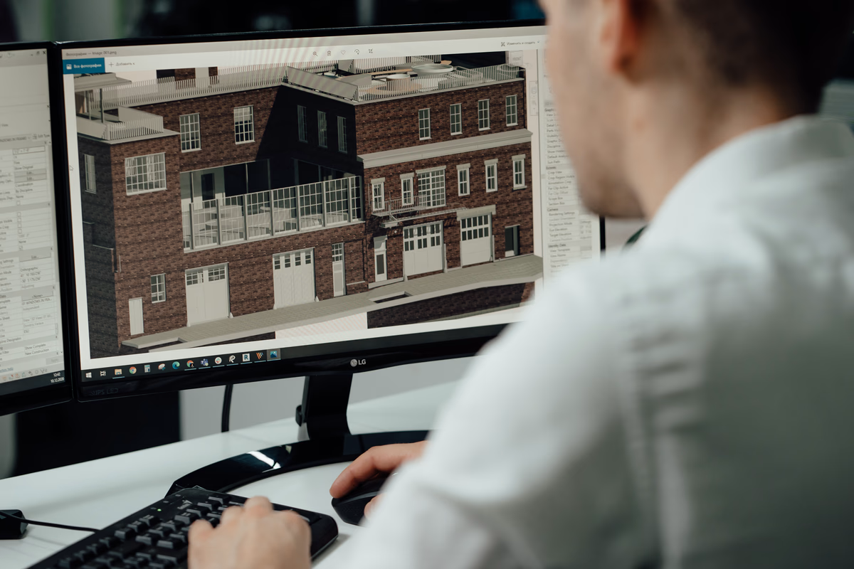
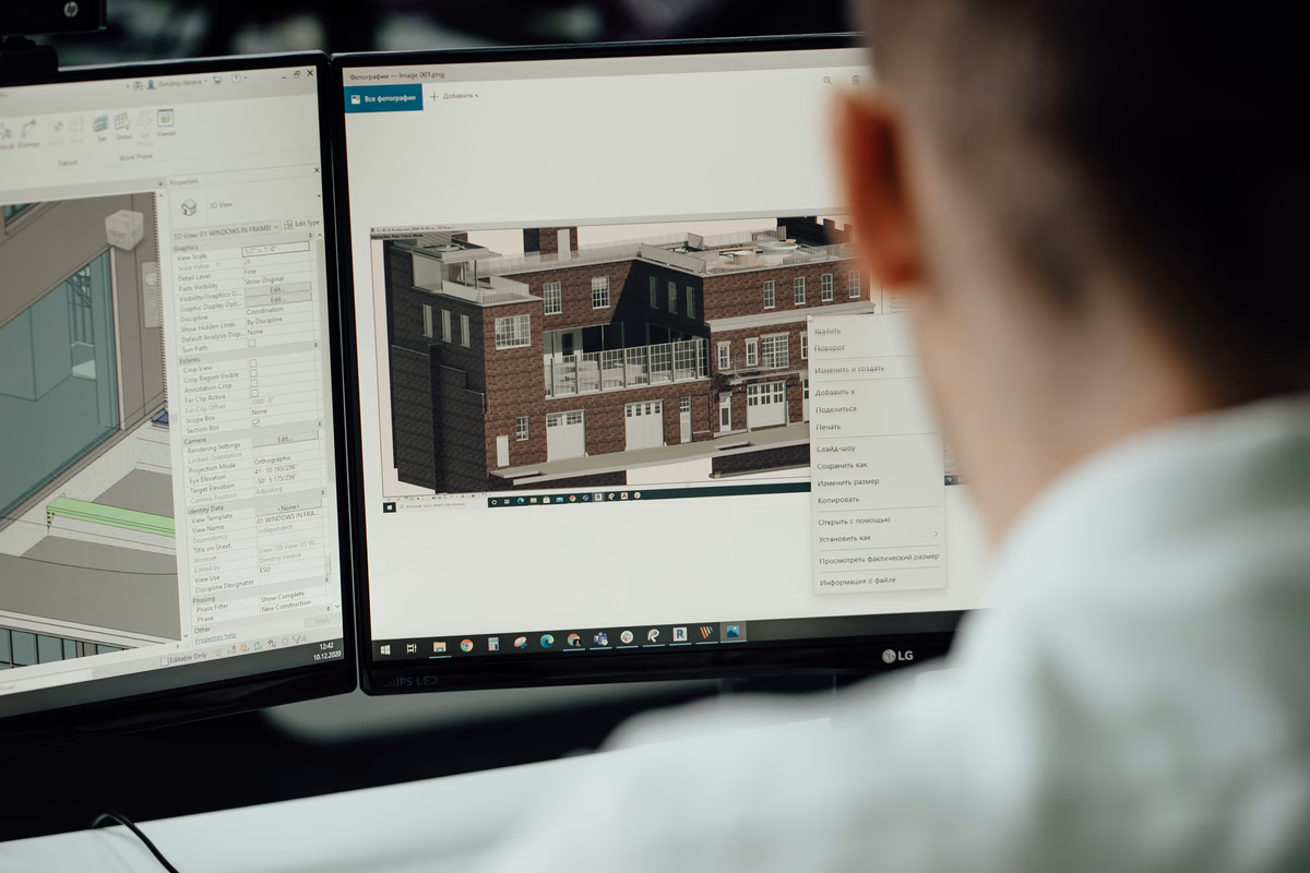
The days of hand-drawn blueprints are long gone. Today, software like AutoCAD, Tekla Structures, and Revit makes creating fabrication drawings faster and smarter. These tools automate tedious tasks, like checking dimensions, and flag errors before they reach the workshop.
BIM takes it to another level. It turns drawings into 3D models you can explore, rotate, and test for clashes – like a beam hitting a pipe – before any steel is cut. This saves time and money by fixing issues virtually.
Scan-to-BIM is a lifesaver for renovations. It uses laser scans to create models of existing structures, turning them into accurate drawings when old plans are missing. For prefabrication, drawings feed directly into CNC machines, ensuring cuts are exact.
Automation, like scripting for repetitive tasks, can speed up detailing by hours. It’s not about replacing people; it’s about letting them focus on the tough stuff while tech handles the routine.
Practical Tips for Crafting Stellar Drawings
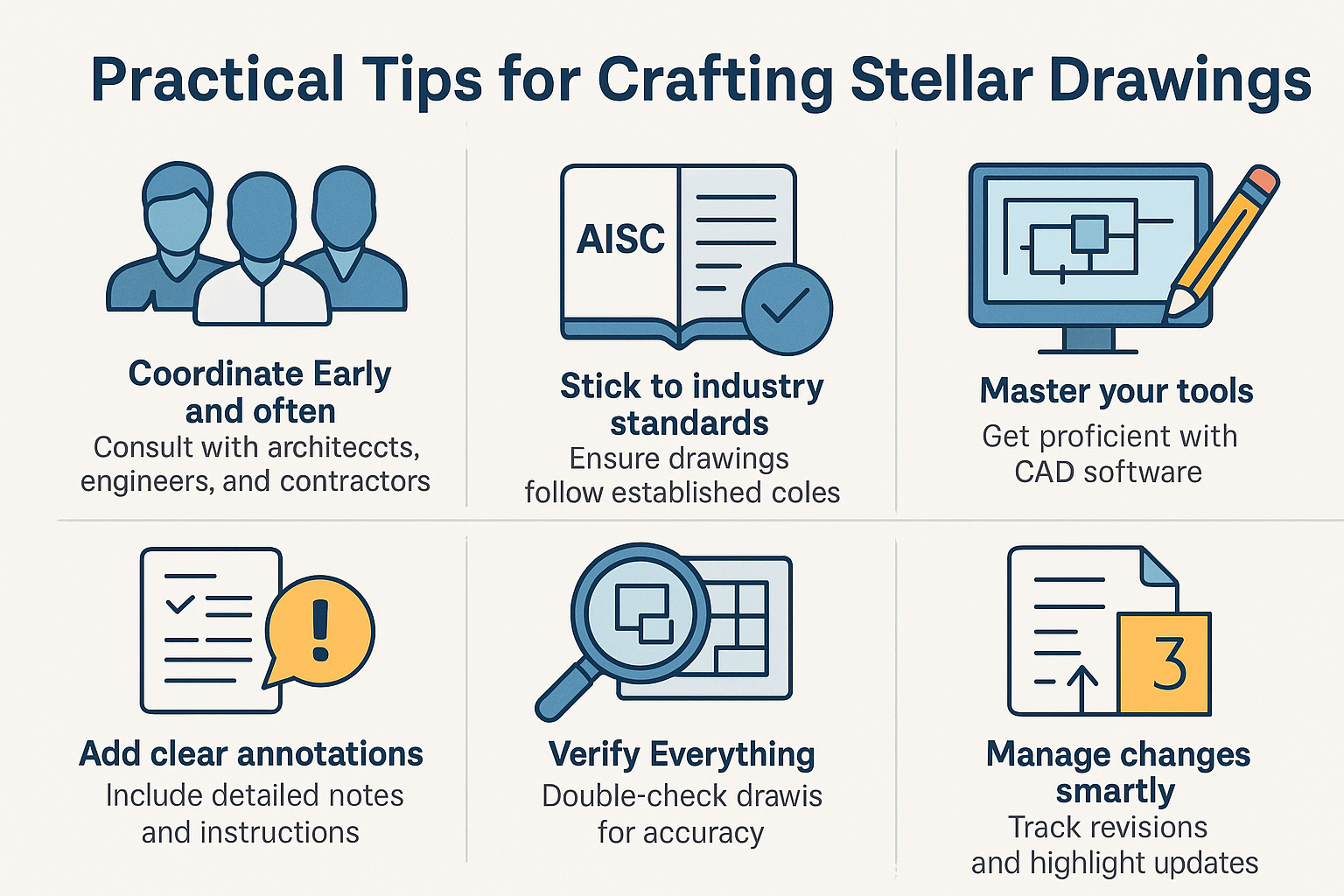
Making great steel fabrication drawings takes more than software – it’s about process and attention to detail. Here’s what I’ve learned works best:
Coordinate Early and Often
Talk to architects, engineers, and contractors upfront. This catches design quirks – like load requirements or aesthetic needs – that shape the drawings.
Stick to Industry Standards
Use codes like AISC (in the US) or Eurocode (in Europe) for consistent labeling and notation. It makes drawings universally clear and compliant.
Master Your Tools
Get comfortable with CAD software features, like auto-detailing or error checks. Templates can speed up common tasks without cutting corners.
Add Clear Annotations
Include notes for anything tricky, like weld quality or special handling. Clear instructions prevent fabricators from guessing.
Verify Everything
Double-check drawings against the original design. A second look catches small errors that could become big problems.
Manage Changes Smartly
Track revisions with version numbers, dates, and highlighted changes. It keeps everyone on the same page when updates happen.
- Collaborate with stakeholders to align goals.
- Follow standards for clarity and compliance.
- Use software efficiently to save time.
- Annotate thoroughly to avoid missteps.
- Verify for accuracy before finalizing.
- Track revisions clearly to manage updates.
These steps build drawings you can trust, whether you’re a freelancer or part of a bigger team.
Avoiding Common Mistakes
Even the best hit snags. Tight deadlines can lead to rushed drawings, so plan with buffers and use project management tools to stay on track. Keep communication open with clients to manage expectations.
Outdated standards are another trap. Stay current with training or industry updates to avoid compliance issues. Overcomplicating drawings wastes time – stick to what’s needed, using templates for efficiency.
Complex projects risk mismatches, like misaligned connections. Digital tools like BIM clash detection catch these early. If workloads spike, outsourcing can bring fresh expertise without long-term costs.
Mistakes happen, but treating them as chances to improve keeps projects moving forward smoothly.
When Outsourcing Makes Sense
Not every team needs an in-house drafter. Outsourcing saves on salaries, software, and training, paying only for what you use. It’s great for accessing specialists who know the latest CAD tools, ensuring high-quality results.
It also flexes with project demands – scale up for big jobs, down for quiet times. Pricing varies: hourly rates suit quick tasks, while fixed fees work for defined scopes. Complex drawings, like those with 3D modeling, cost more.
Set clear terms upfront – scope, revisions, software – to avoid surprises. It’s about finding a partner who delivers reliable drawings without the overhead.
Where These Drawings Shine
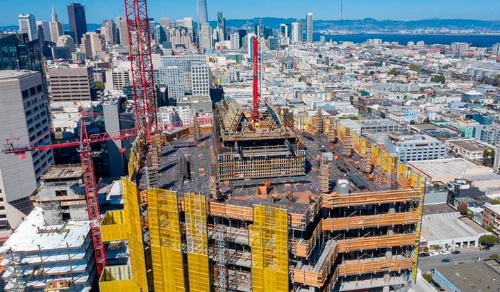
Steel fabrication drawings are versatile, proving their worth across project types. In skyscrapers, they detail beams for stability under massive loads. Bridges rely on them for connections that withstand wind and rain.
Industrial plants use them for custom frames that fit machinery like a glove. Even smaller residential projects, like steel staircases, benefit from their precision, ensuring quick installs.
Automation, like generating drawings for prefab, cuts production time, while 3D models enhance accuracy in complex builds, proving their value everywhere.
What’s Next for Fabrication Drawings
The future’s exciting. AI-driven generative design is emerging, suggesting optimized shapes that drawings can incorporate for innovative structures. Sustainability is pushing for less waste, with drawings optimizing material use.
Cloud collaboration is speeding up teamwork, letting multiple parties edit drawings in real-time. These trends are making drawings not just tools but strategic assets for smarter construction.
Closing Thoughts: Getting Started
Steel fabrication drawings are the backbone of any steel-based project, blending precision with practicality to deliver results. Start by evaluating your project’s scope, embrace tech like BIM for an edge, and consider outsourcing if you need specialized skills.
Good drawings don’t just guide construction – they save time, cut costs, and keep your project on solid ground. Get them right, and you’re setting up for success from the first cut to the final bolt.
FAQs
How do steel fabrication drawings differ from regular blueprints?
Fabrication drawings are more detailed, focusing on specific steel components with precise instructions for cutting, joining, and assembly, while blueprints offer a broader overview of the entire project.
Why are tolerances so important in these drawings?
Tolerances define acceptable variations in measurements, ensuring parts are practical to make without compromising structural integrity – too strict, and production stalls; too loose, and safety suffers.
How does BIM improve steel fabrication drawings?
BIM turns drawings into 3D models, allowing virtual testing for clashes, automating tasks, and improving coordination, which reduces errors and speeds up the construction process.
When is outsourcing fabrication drawings a good idea?
Outsourcing is ideal when you lack in-house expertise, face tight deadlines, or need cost-effective access to advanced tools and skilled drafters, especially for complex or one-off projects.
Our Case Studies
We have handled 200+ BIM & VDC projects for commercial, industrial, and residential sectors.
Our work includes:
Formwork design automation
Our client from
California, USA
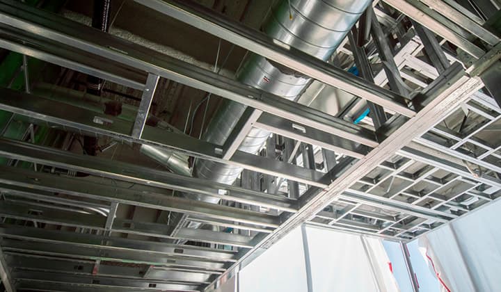
Suspended ceiling design automation
Our client from
New York, USA
Wall framing design automation
Our client from
California, USA