هل لديك أي أسئلة؟ اتصل بنا!
انضم إلى فريقنا!
اطلب عرض أسعار أو استشارة مجانية

Reading construction plans involves understanding standardized symbols, scales, and drawing types used to communicate building designs. Start with the title block and cover sheet, then work through architectural, structural, and MEP drawings systematically, paying attention to dimensions, notes, and specifications that define how the project should be built.
Construction plans are the universal language of the building industry. Whether you’re a contractor, engineer, tradesperson, or project manager, the ability to interpret these technical documents accurately determines project success.
But here’s the thing—construction drawings can feel overwhelming at first glance. Lines, symbols, abbreviations, and multiple sheet types create complexity that intimidates newcomers. The good news? Once you understand the foundational elements, reading plans becomes systematic and logical.
What Are Construction Plans?
Construction plans (often called blueprints or construction drawings) are technical documents that communicate design intent to builders. They contain scaled drawings, specifications, dimensions, and notes that define every aspect of a construction project.
These documents serve as the legal contract between design and execution. According to BuildSync, design-related issues (including specification errors and omissions) cause up to 70% of rework costs, with rework accounting for 4-10% of total construction costs. Clear plan reading prevents expensive mistakes.
Plans aren’t just drawings—they work alongside written specifications that detail materials, quality standards, and installation methods. Together, they form complete construction documentation.
Understanding the Cover Sheet and Title Block
Always start with the cover sheet. This introductory page lists all drawings in the set, establishes sheet numbering systems, and provides project overview information.
The title block appears on every sheet (usually bottom-right corner) and contains critical information:
- Project name and address
- Drawing title and number
- Scale of the drawing
- Date of issue and revision history
- Design firm and contact information
- Approval stamps and signatures
Real talk: Always check the revision date. Working from outdated drawings is one of the most common—and most costly—mistakes on construction sites.
Get Practical BIM Project Support

باورخ works with construction and design teams that need outside help with BIM production. The company provides BIM modeling, BIM coordination, Scan to BIM, BIM automation, prefabrication workflows, and structural detailing. The focus stays on execution – delivering the models, drawings, and technical outputs projects depend on.
Looking for a Team to Support BIM Production?
Talk with Powerkh to:
- create BIM models and project documentation
- process scan data into structured outputs
- assist with coordination, detailing, and automation work
👉 Contact Powerkh for a project review and consultation.
Types of Construction Drawings
Construction projects use multiple drawing types, each serving specific purposes. Understanding what information lives where makes navigation much easier.
| Drawing Type | الغرض | Key Information |
|---|---|---|
| Architectural | Building layout and design | Floor plans, elevations, room layouts, finishes |
| Structural | Load-bearing systems | Foundation, framing, beams, columns, reinforcement |
| Mechanical | HVAC systems | Ductwork, equipment locations, air distribution |
| Electrical | Power and lighting | Circuits, panels, fixtures, switches, outlets |
| السباكة | Water and waste systems | Pipe routing, fixtures, drains, water supply |
| Civil | Site work | Grading, drainage, utilities, paving |
Sheet numbering follows standard conventions: A for Architectural, S for Structural, M for Mechanical, E for Electrical, P for Plumbing. The system makes specific information easy to locate quickly.
Decoding Scales and Dimensions
Scale indicates the ratio between the drawing and actual construction. Common scales include 1/4″ = 1′-0″ (meaning one-quarter inch on paper equals one foot in reality) or 1:100 in metric systems.
But wait. Don’t scale dimensions with a ruler. Always use the written dimensions provided on the drawing. Why? Plans may be printed at different sizes, and scaling introduces measurement errors.
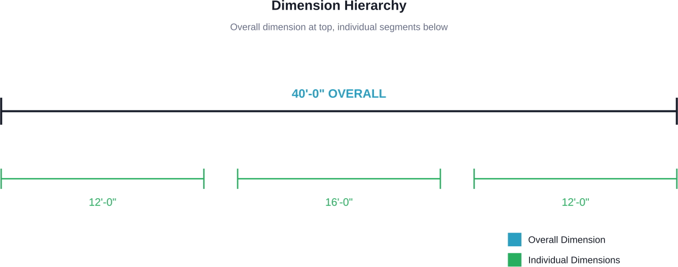
Dimensions show three key measurements:
- Overall dimensions: Total length/width of walls or spaces
- Running dimensions: Cumulative measurements along a continuous line
- Individual dimensions: Specific distances between elements
When dimensions conflict, notes on the drawing establish priority—typically written dimensions override scaled measurements.
Common Symbols and Abbreviations
Construction drawings use standardized symbols to represent building elements. Learning these symbols is essential for accurate plan interpretation.
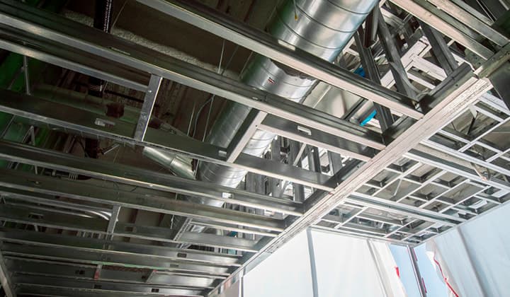
Walls appear as parallel lines (thickness indicates wall type). Doors show as openings with arcs indicating swing direction. Windows are represented by parallel lines with glass shown as a single line between frames.
Common abbreviations include:
- CLG = Ceiling
- FLR = Floor
- TYP = Typical
- EQ = Equal
- NTS = Not to Scale
- CMU = Concrete Masonry Unit
- GWB = Gypsum Wall Board
Most drawing sets include a symbol legend—usually on the first few sheets or within the general notes section.
Reading Different Plan Views
Plans use various viewing angles to communicate three-dimensional information on two-dimensional paper.
- مخططات الطوابق: Horizontal cuts through the building showing room layouts, walls, doors, and windows from above. Think of it as slicing through the building at window height and looking down.
- الارتفاعات: Vertical views of exterior or interior walls showing height relationships, materials, and vertical dimensions. These show what you’d see standing perpendicular to a wall.
- الأقسام: Vertical cuts through the building revealing internal construction, floor-to-floor heights, and assembly details. Sections show what’s hidden inside walls and floors.
- Details: Enlarged views of specific connections or assemblies, typically drawn at larger scales like 1″ = 1′-0″ or 3″ = 1′-0″ for clarity.
Notes and Specifications Matter
General notes and specific callouts provide information that can’t be conveyed through drawings alone. Many experts suggest that missing these notes causes more field problems than symbol misinterpretation.
General notes apply to the entire project or drawing type. Specific notes (connected to elements with leaders or callout bubbles) apply only to tagged items.
Specifications work alongside drawings. According to ASTM E1699 standards for value engineering, performing value engineering during schematic design (up to 15% design completion) minimizes miscommunication and redesign.
When drawings and specifications conflict, most contracts establish that specifications take precedence—but always verify this hierarchy in your contract documents.
Cross-Referencing Between Sheets
Construction drawings interconnect through reference symbols. A detail bubble shows a circle with two numbers: the detail number above and the sheet number below where that detail appears.
Section cut symbols use similar notation—arrows point to the viewing direction, with numbers indicating which sheet contains that section view.
Following these references is critical. The floor plan might show a wall, but the detail on another sheet reveals the specific assembly, materials, and connections required.
Start Reading Plans Confidently
Reading construction plans is a learnable skill that opens doors across the construction industry. Start with the fundamentals—understand the cover sheet organization, master common symbols, respect scale and dimensions, and follow cross-references systematically.
Practice makes perfect. Request sample plan sets, study completed projects, and compare drawings to finished buildings when possible. The connection between lines on paper and three-dimensional reality becomes clearer with each set you review.
Don’t rush. Experienced professionals still spend significant time studying plans before breaking ground. Thorough plan review prevents expensive mistakes and builds the foundation for successful project execution.
الأسئلة الشائعة
What’s the difference between blueprints and construction plans?
The terms are used interchangeably today, though “blueprints” originally referred to the blue-and-white reproduction process. Modern construction plans are typically printed on white paper or viewed digitally, but the name “blueprint” persists in common usage.
Do I need special training to read construction plans?
Formal training helps, but many tradespeople learn through on-the-job experience. Online courses and community college programs offer structured blueprint reading education. Basic literacy can be self-taught using practice sets and guides.
How long does it take to learn blueprint reading?
Basic comprehension takes weeks of study and practice. Proficiency develops over months of regular exposure. Mastery—understanding complex assemblies and catching errors—typically requires years of field experience across multiple projects.
What scale is most common for floor plans?
Residential and commercial floor plans typically use 1/4″ = 1′-0″ scale in imperial measurements or 1:50 or 1:100 in metric. Larger buildings might use 1/8″ = 1′-0″ to fit on standard sheet sizes.
How do I handle conflicting information between drawings?
Check the project manual or general conditions—most contracts establish precedence hierarchies. Generally, larger-scale drawings override smaller scales, dimensions override scaling, and specifications override drawings. Always request a Request for Information (RFI) when conflicts create ambiguity.
Can I learn to read plans without construction experience?
Absolutely. Understanding the visual language of construction drawings doesn’t require field experience, though practical knowledge helps contextualize what you’re reading. Many architects, engineers, and estimators read plans expertly without swinging hammers.
What software do professionals use to view digital plans?
PDF readers handle most digital plan viewing. Specialized software like Bluebeam Revu, PlanGrid, or Autodesk Construction Cloud adds markup, measurement, and collaboration features. CAD programs like AutoCAD open native drawing files but require more technical expertise.

دراسات الحالة لدينا
لقد تعاملنا مع أكثر من 200 مشروع من مشاريع نمذجة معلومات المباني ونمذجة معلومات المباني للقطاعات التجارية والصناعية والسكنية.
يشمل عملنا ما يلي:
أتمتة تصميم القوالب
Our client from
California, USA
أتمتة تصميم السقف المعلق
Our client from
New York, USA
أتمتة تصميم إطارات الحائط
Our client from
California, USA